TAD550GE, TAD551GE, TAD750GE, TAD751GE
Tools:
885812 Timing tool
9998681 Rotation tool
88800014 Rotation tool

NOTICE! Normal valve clearance is set when the Volvo engine is cold, or when it has been left to cool for at least a half hour. Oil temperature < 80 °C (176 °F).
IMPORTANT!
Clean thoroughly before dismantling.
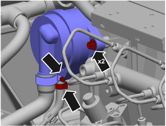
1 Disconnect the ventilation hoses.
Remove the oil trap.
2 Remove the harness from the protective cover.

Remove the protective cover.
Remove the valve cover.
3 Remove the engine control unit according to
Engine Control Unit (ECU), Replace page 212.
4 Remove the flywheel access cover.

5 Install 9998681 Rotation tool.

6 Adjust the valve clearance (cylinder 1 overlapping)
Rotate the crankshaft so that piston # 1 is at TDC and the exhaust and inlet valves overlap on cylinder # 1.
NOTICE! None of the push rods for this cylinder should be rotatable in this position.

7 Adjust the valve clearance for each cylinder according to Valve clearance, settings 1 Undo the adjuster screw locking nut (1) on the rocker arm.

2 Fit 885812 Timing tool (2), to the adjuster screw (3).
3 Turn the adjuster screw (3) until zero clearance is obtained between the rocker arm and the valve.
4 Zero the protractor.
5 Turn the adjuster screw (3)
- Counterclockwise 90° for the inlet valve.
- Counterclockwise 150° for the exhaust valve.
6 Counterhold the adjuster screw (3) while tightening the locking nut (1).
Tightening torque: 20 Nm (14.8 lbf. ft.)
8 Valve clearance (cold engine), settings
Set the valve clearance for each cylinder according to the illustrated angles.
Inlet: Counterclockwise 90° (Cyl. 3, 5, 6)
Exhaust: Counterclockwise 150° (Cyl. 2, 4,6)

9 Adjust the valve clearance for the other valves (cylinder # 6 overlapping)
Rotate the crankshaft 360° (one revolution) until the exhaust and inlet valves on cylinder # 6 overlap.
NOTICE! None of the push rods for this cylinder should be rotatable in this position.
10 Set the valve clearance for each cylinder according to the illustrated angles.
Inlet: Counterclockwise 90° (Cyl. 1, 2, 4)
Exhaust: Counterclockwise 150° (Cyl. 1, 3,5)

11 Remove 9998681 Rotation tool and replace the flywheel access cover.
12 Check the valve cover gasket.

13 Install the valve cover.
Tightening torque: 30 Nm (22.1 lbf. ft.)
Tightening sequence: Diagonal
Attach the harness to the protective cover.
Install the protective cover.

14 Install the oil trap and the crank case ventilation hoses.

15 Carry out a function check.
Valves, Adjustment
TAD752GE, TAD753GE, TAD754GE
Tools:
885812 Timing tool
88800014 Rotation tool
NOTICE! Normal valve clearance is set when the engine is cold, or when it has been left to cool for at mleast a half hour. Oil temperature < 80 °C
IMPORTANT!
Clean thoroughly before dismantling.
1 Remove the oil trap.

2 Remove the valve cover.

3 Remove the plug from the flywheel.
Install 88800014 Rotation tool.

4 Set valve clearance (cylinder 1 overlapping)
Rotate the crankshaft so that piston # 1 is at TDC and the exhaust and inlet valves overlap on cylinder # 1.
None of the push rods for this cylinder should be able to be rotated in this position.

5 Adjust the valve clearance for each cylinder according to: Valve clearance, settings
1 Loosen the adjuster screw locking nut (1) on the rocker arm.
2 Fit 885812 Timing tool to the adjuster screw (3).
3 Turn the adjuster screw (3) until zero clearance is obtained between the rocker arm and the valve.
4 Zero the protractor.
5 Turn the adjuster screw (3).
• Counterclockwise 75° for the inlet valve.
• Counterclockwise 105° for the exhaust valve.

6 Counterhold the adjuster screw (3) while tightening the locking nut (1).
Tightening torque: 20 Nm (14.8 lbf. ft.)

6 Valve clearance (cold engine), setting:
Inlet: Counterclockwise 75° (Cyl. 3, 5, 6)
Exhaust: Counterclockwise 105° (Cyl. 2, 4,6)
7 Adjust the valve clearance for the other valves (cylinder no. 6 overlapping) Crank the crankshaft 360° (one revolution) until the exhaust and inlet valves on cylinder no. 6 overlap.

None of the push rods for this cylinder should be able to be rotated in this position.
8 Set the valve clearance for each cylinder according to the illustrated angles.
Inlet: Counterclockwise 75° (Cyl. 1, 2, 4)
Exhaust: Counter clockwise 105 (cyl. 1, 3,5)

9 Remove 88800014 Rotation tool and replace the plug in the flywheel.
10 Install the valve cover.
Tightening torque: 8.5 Nm (6.3 lbf. ft.)

11 Install the oil trap.

Copyright © Guangxi Dingbo Generator Set Manufacturing Co., Ltd. All Rights Reserved | Sitemap
Update cookies preferences