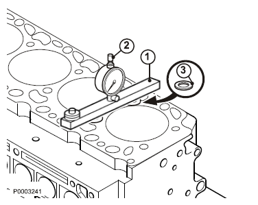
 The object of the measurement is to determine selection of the cylinder head gasket. Clean the mating surface, the cylinder block sealing surfaces and the cylinder head. Use cleaning spirits and 885516 Gasket scraper. Install spacers (3) and 9998678 Gauge rod (1) on the engine block sealing surface. Set the dial indicator (2) to ”0”.
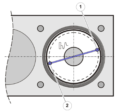
15 NOTICE! All pistons must be measured at TDC. Piston height above the Volvo engine block must be measured at measuring points (1) and (2) on all pistons. Pay attention to the measuring points, since the piston crown is domed.

16 Check that the piston is in its uppermost position, TDC. Place the dial indicator on the piston at measuring points (1) and (2). Read off and note the value on the dial indicator.

17 Compare the highest noted value with the table below. Determine the appropriate cylinder head gasket.
Piston height: | Marking (1): |
0.28 - < 0.54 mm (0.011 - < 0.021") | 1 hole, gasket 1.42 mm (0.056") |
0.54 - < 0.64 mm (0.021 - < 0.025") | 2 holes, gasket 1.52 mm (0.060") |
0.64 - < 0.75 mm (0.025 - < 0.030") | 3 holes, gasket 1.62 mm (0.064") |

18 NOTICE! Check the contact surface before installation. Pay attention to the guide sleeves (1).

19 Position the cylinder head gasket with the marking toward the flywheel.

20 Lift the cylinder head into place. Pay attention to the guide sleeves.

21 NOTICE! Use new cylinder head bolts.
Lubricate the cylinder head bolts. Install the cylinder head bolts.
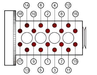
NOTICE! Tighten the bolts in in sequence, as
illustrated.
Tighten in three steps:
Step 1: 50 Nm (36.9 lbf. ft.)
Step 2: 130 Nm (95.9 lbf. ft.)
Step 3: 90°


22 Install the pushrods.

Rocker arm bridges and rocker arms,
installation
23 NOTICE! The push rods must not be under compression due to valve overlap during installation.
Install the rocker bridge with rocker arms. Align it with the pushrods and valves.
Tightening torque: 30 Nm (22.1 lbf. ft.)

24 Connect the fuel return line (1). Hold the adapter secure (2) and fit the hollow screw (3).
Tightening torque: 29 Nm (21.4 lbf. ft.)

25 Set the valve clearance according to Valves, Adjustment page 49.
26 Install the injectors according to Injector, Change page 123.
27 Install the common rail unit according to 23-7, Common Rail, Change.
28 Install the inlet manifold according to Intake Manifold, Change page 143.
29 Install the exhaust manifold according to Exhaust Manifold, Change page 152.
30 Install the turbocharger according to Turbo, Change page 174.
31 Install the thermostat housing according to 26-2, Thermostat Housing, Change.
32 Install the air filter housing.
33 Install new oil filters and fill with engine oil according to Oil filter, Change page 94.
34 Fill with coolant according to Coolant, Change page 187.
35 Turn the main switch on.
36 Start the engine and perform a function check.
TAD752GE, TAD753GE, TAD754GE
Tools:
885516 Gasket scraper
9998678 Gauge rod
NOTICE! The main switch must be in the off position before work is begun.
1 Cooling system drained; refer to Coolant, Change page 187.
2 Oil drained.
Removal
3 Remove the air filter housing.
4 Remove the turbocharger according to Turbo, Change page 174.
5 Remove the exhaust manifold; refer to Exhaust
Manifold, Change page 152.
6 Remove the inlet manifold; refer to Intake Manifold, Change page 143.
7 Remove the thermostat housing; refer to 26-2, Thermostat Housing, Change.
IMPORTANT!
Work on the fuel system demands exceptional cleanliness. Install protective plugs in open connections.
8 Remove the common rail unit according to 23-7, Common Rail, Change.
9 Remove the injectors; refer to Injector, Change page 123.
Rocker arm bridge, removal
10 Remove the cable holders (2 pcs.) and move them aside.
11 Undo the rocker arm bridge bolts alternately.
12 Remove the rocker arm bridge with rocker arms.
13 Mark up the valve yokes.
14 Remove the push rods (1).
15 Remove the valve yokes (2).
16 Remove the wiring connectors (1) and the cable holder nuts (2).
17 Lift away the wiring.
18 Remove the injector sleeve.
19 Remove the cylinder head bolts.
20 Attach a lifting eye to the front of the cylinder head.
21 Connect straps to the lifting eyes and lift the cylinder head to remove it.
Cylinder head gasket
22 The object of the measurement is to determine the selection of cylinder head gasket.
23 Clean the mating surface, the cylinder block sealing surfaces and the cylinder head. Use cleaning spirits and 885516 Gasket scraper.
24 Place spacing washers (3), 9998678 Gauge rod
(1) on the engine block sealing surface and set the dial indicator (2) to ”0”.
NOTICE! All pistons must be measured at TDC. 25 Piston height above the engine block must be
measured at two points (1) and (2) on all pistons. Pay attention to the measuring points, since the
piston crown is domed.
26 Check that the piston is in its uppermost position, TDC.
Place the dial indicator on the piston at measuring points (1) and (2).
Read off and note the value on the dial indicator.
27 Compare the highest noted value with the table below. Decide on the suitable cylinder head gasket.
Piston height: | Marking (1): |
0.31 - 0.40 mm (0.0122-0.0157") | 1 hole, gasket 1.15 mm (0.0453") |
(0.0161-0.0197") | 2 holes, gasket 1.25 mm (0.0492") |
NOTICE! Make sure the surface is clean before application. 28 Position the cylinder head gasket with the marking toward the flywheel.
Pay attention to the guide sleeves (1).
29 Lift the cylinder head into place. Pay attention to the guide sleeves.
NOTICE! Use new cylinder head bolts.
30 Lubricate the cylinder head bolts.
31 Install the cylinder head bolts.
NOTICE! Tighten the bolts in numerical order, as illustrated.
32 Tighten in three steps:
Step 1: 40 Nm (29.5 lbf.ft.)
Step 2: 95 Nm (70.1 lbf.ft.)
Step 3: 180°
33 Install the injector sleeve.
34 Check the harness seal.
35 Fit the wiring connectors (1) with lock washers, and tighten the plastic nuts (2).
36 Connect the harness terminal to the wiring connector
(1).
37 Allow the cable holder to hang free from the engine.
38 Fit the push rods (1).
39 Lubricate the valve stems.
40 Replace the valve yoke (2) in accordance with the earlier marking.
Copyright © Guangxi Dingbo Generator Set Manufacturing Co., Ltd. All Rights Reserved | Sitemap
Update cookies preferences