Compression Test
TAD550GE, TAD551GE, TAD750GE, TAD751GE
Tools:
9988539 Compression meter
9998694 Adapter
 Removal
1 Check, and where necessary adjust, valve clearances according to Valves, Adjustment page 49.
2 Remove the injectors; refer to Injector, Change page 123.
3 Remove the electrical connection to the control valve.
 Compression test
NOTICE! The retaining brackets must be installed together with the adapters on cylinders 1-5.
4 Install 9998694 Adapter (1).
Use the existing retaining bracket (2).
Tighten the bolt (3).
Tightening torque: 20 Nm (14.8 lbf. ft.)
NOTICE! Do not run the starter motor for more than 15 seconds at a time; allow an interval of 60 seconds between each operation.

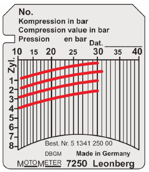
5 Attach 9988539 Compression meter to the adapter on the first cylinder.
• Check that the gear is in the neutral position.
• Crank the engine with the starter motor until the needle on the compression tester ceases to move (max compression value).
• Read off the value.
Compression: 30-38 bar (435-551 psi)
• Move the compression tester to the next cylinder.
• Repeat the test on all cylinders.
 NOTICE! Differences of 10 % between cylinders are fully acceptable and are not cause for actions such as valve renovation.
If the pressure difference exceeds 15 %, the cylinder in question should be disassembled to determine the cause.
Installation.
6 Install the injectors; refer to Injector,
Change page 123.
7 Install the electrical connection to the control valve.
8 Perform a leakage and function check.
Compression Test
TAD752GE, TAD753GE, TAD754GE
Tools:
9988539 Compression meter
21699246 Adapter
Removal
1 Check, and where necessary adjust, valve clearances according to Valves, Adjustment page 49.
2 Remove the injectors; refer to Injector,
Change page 123.
3 Remove the injectors; refer to Fuel Feed Pump,
Change page 120.
4 Remove the electrical connection to the control
valve.
Engine Fixture, Installation
Tools:
885510 Plugs
9986485 Stand
88800050 Fixture

Removal
1 Remove the turbocharger according to Turbo, Change page 174.
NOTICE! Fit protective plugs (885510 Plugs) to all of the turbocharger connections.
2 Fit protection plugs in the return and delivery pipe connections.
3 Remove the cable clamps and move the harness aside.
4 Remove the radiator assembly according to 26-1, Radiator Assembly (Complete Unit), Change.
5 Remove the air filter housing

Engine fixture, installation
NOTICE! The bolts must be replaced every time an engine block is installed. 6 Install 88800050 Fixture and fasten it using the above-mentioned bolts, grade 12.9.
• M8x40 (5 pcs)
Tightening torque: 40 Nm (29.5 lbf.ft.)
7 Connect the lifting device to the engine lifting lugs. Install the engine in 9986485 Stand.

Engine fixture removal
8 Connect the lifting device to the engine lifting lugs. Remove the engine from 9986485 Stand.
9 Remove the fixture.
Scrap used bolts.
Installation
10 Install the radiator assembly according to 26-1, Radiator Assembly (Complete Unit), Change.
11 Install the cable clamps and move the harness back.
12 Remove the protective plugs.
13 Install the turbocharger according to Turbo, Change page 174.
14 Install the air filter housing.
P0015276
21-0 Engine Complete, General
Cylinder Head, Removal
TAD550GE, TAD551GE, TAD750GE, TAD751GE
Tools:
885516 Gasket scraper
9998678 Gauge rod
NOTICE! Turn off the main switch before any work is carried out.
Cooling system drained; refer to Coolant, Change page 187.
Oil drained.
Removal
1 Remove the thermostat housing according to26-2, Thermostat Housing, Change.
2 Remove the turbocharger according to Turbo, Change page 174.
3 Remove the exhaust manifold according to Exhaust Manifold, Change page 152.
4 IMPORTANT!
Working with the fuel system requests special cleanliness.
Install safety plugs in open connections.
Remove the common rail unit according to 23-7, Common Rail, Change.
5 Remove the injectors according to Injector, Change page 123.
Rocker arm bridge with rocker arms, removal
6 Remove the rocker arm bridges with rocker arms

7 Remove the push rods.

8 Inspect the rocker arm bridge. For disassembly and inspection, refer to 21-6, Rocker arm bridge, disassembly.

9 Remove the inlet manifold according to Intake Manifold, Change page 143.

10 Undo the fuel return hose connections (1). Hold the adapter secure (2) and remove the hollow screw (3).
11 Remove the cylinder head bolts.

12 Lift off the cylinder head.


13 Remove the main cylinder head gasket.
Copyright © Guangxi Dingbo Generator Set Manufacturing Co., Ltd. All Rights Reserved | Sitemap
Update cookies preferences