The injection pump is called the "heart" of the diesel generator set, which shows the importance of the fuel injection pump of the diesel generator unit. It is the most important component of the diesel fuel supply system. Its function is to increase the pressure of the diesel generator set and to supply fuel to the fuel chamber on a regular and quantitative basis according to the requirements of the working process of the diesel generator set.

Figure 1. 6 cylinder B series injection pump assembly

Figure 2. 12 cylinder B series injection pump assembly
The main structure of the 4, 6, and 12-cylinder fuel injection pump is basically the same (as shown in FIGS. 1 and 2) except the number of cylinders, and is a multi-cylinder composite type. It is composed of the fuel injection pump body, the sub-pump, the transmission mechanism and the oil quantity control mechanism.
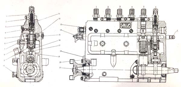
Each pump mainly consists of oil supply valve tight seat, oil supply valve spring, oil supply valve couple, plunger coupling, spring upper seat, spring lower seat, plunger spring, oil quantity control sleeve, adjusting gear, rolling wheel parts and so on, as shown in figure 3.

Figure 3. 6 Assembly profile of cylinder B Series injection pumps
Above illustration:
1- oil outlet valve tight seat; 2-oil valve spring; 3-oil outlet valve coupling; 4-sleeve positioning nail; 5-lock screw; 6-oil quantity control sleeve; 7-spring upper seat; 8-plunger spring; 9-spring lower seat; Keywords 10- oil level screw; 11- pump body; 12- adjusting tooth rod; 13- outlet screw; 14- oil limiting screw; 15- plunger coupling; 16- timing adjusting screw; 17- timing adjusting nut; 18- adjusting gasket; 19- roller body assembly; 20- Shaft cover parts; 21- Camshaft
The oil supply valve couple part is the relief type oil delivery valve. Plunger coupling and oil supply valve pair are mutually developed, the user is absolutely not allowed to replace the single piece in repair, disassembly and replacement.
The oil supply principle of the fuel injection pump of the diesel generator set is shown in Figure 4. When the plunger is in the lower stop position, the two oil holes on the plunger sleeve are open, the space on the upper part of the plunger is communicated with the oil channel in the oil pump body, and the inner cavity of the plunger sleeve is filled with fuel, as shown in Fig. 5a. As the plunger moves upward, a portion of the fuel is squeezed and poured into the oil passage, which process continues until the top surface of the plunger passes over the upper edge of the oil hole, as shown in FIG. 5b. Since then the plunger continues to move upward, the fuel pressure in the chamber increases sharply, the oil delivery valve is opened, and the fuel is pressed into the high pressure tubing through the tight seat of the oil delivery valve. As the plunger continues to move up, the fuel pressure of the high pressure tubing and injector is greatly increased. When the pressure exceeds the opening pressure of the injector, the injector needle valve opens itself and the high pressure fuel begins to be injected into the combustion chamber, as shown in figure 5c. The plunger feed continues until the screw edge of the plunger reaches the lower edge of the plunger casing hole, as shown in figure 5d. When the oil hole of the plunger sleeve is opened, the injector fuel injector stops. The high-pressure fuel oil flows back to the low pressure chamber of the pump body through the oil holes in the plunger's straight grooves and plunger sleeve. As shown in figure 5e, the space above the plunger and the pressure in the tubing are reduced, and the oil supply valve falls to the valve seat under the action of the spring. When the plunger moves downward under the action of the spring, the space above the plunger in the plunger sleeve is filled with fuel again, ready for the next working cycle.

The amount of oil in the injection pump of the diesel generator set depends on the relative position of the plunger and the plunger sleeve, and rotating the plunger can control the fuel supply. When adjusting the movement of the tooth rod, the gear ring and the oil quantity control cylinder drive the plunger to rotate. If the plunger rotates to the right, the oil supply increases and the oil supply decreases, as shown in figure 5fg. Once the plunger tank is connected to the oil hole of the plunger sleeve, stop the oil supply, as shown in figure 5 h.
A-down check point, oil filling; b-oil completion, start oil supply; c-oil supply process; d-oil supply end, start return oil; etop check point, return oil; f- partial oil supply; g-maximum oil supply; h- stop oil supply
The 12 cylinder B injection pump used in 12V135 power station diesel engine is also equipped with a buffer above its front surface. As shown in figure 6, the buffer consists of a shell, a piston, a spring seat, a fuel regulating screw, a refueling and discharging screw, and so on.

1-buffer housing; 2-buffer piston; 3-spring; 4-oil drain plug; 5-adjusting screw; 6-filler plug; 7-connecting rod
During use, the user should often rotate the screw plug to check to make sure the buffer is filled with lubricating oil. When the oil pump rack moves along with the buffer piston through the connecting rod mounted on the top of the rack, the oil in the upper and lower cavity of the buffer automatically reflows back through the needle valve hole of the screw, which plays a buffer role and stabilizes the rotational speed. The position of the adjusting screw shall be sealed by the factory during the bench test.
Copyright © Guangxi Dingbo Generator Set Manufacturing Co., Ltd. All Rights Reserved | Sitemap
Update cookies preferences